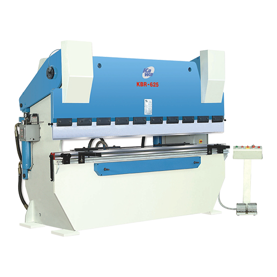
Kawa introduces now premium and state of the art metal forming machinery both for capital good and consumer durable industries. In metal forming section press brake now become an important production equipment, Which has wide application both in capital and consumer goods sector’s. CNC controllers have increased its utility by way of productivity.
Download Technical DataThe main frame and all steel fabricated structure of KAWA Press Brake are made from rolled steel plate IS 2062 grade fabricated monolithic construction with extra reinforcement Et cross ribbings to minimize of deflections.
Ram is so designed for minimum deflection, for parallelism of ram travel without servo/ Hydro electronic etc. a pair of hydraulic cylinders are synchronized by a heavy duty torsion bar made from heavy walled steel tube. Welded to the levers result absolute parallelism between ram and table. Slide is so design with brass liner fitted inside with ram and runs on saddle perfectly housed with frame.
All pins and bushes are made from alloy steel material with hardened ground after machining for accurate and long working life. All Pivots, pin, bushes and slides are lubricated by centralized hand operated lubrication systems.
The Hydraulic Cylinder are made from high resistant steel with chromium plated rod with imported seal kit for perfect and long working life and is so design to change or replace the seal kits without any other dismantling like ram tool etc.
Kawa KBR series Press Brake machine are equipped with punch and die consist with carbon steel material machined and ground but without hardened. Hardened and Ground standard Punch and Die Block or any special tooling can be offer as an optional.
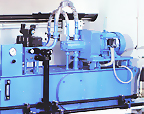
The low noise Hydraulic system is designed as per International practices and assembled with internationally reputed make components. The Hydraulic valves are mounted on the especially compact designed manifold block to minimize of piping and to avoid any leakages. The large size oil reservoir is provided for adequate cooling and increase oil life.
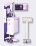
The Kawa press brake machine is facilitate with 3 working mode Inching, Single Stroke and Continuous operation, consist with electrical hard wiring logic of electrical panel. Electrical panels Et components are provided as per international reputed brands.
Inching: This mode is used for setting blade angle depth stroke. The ram movement (up down) can be controlled at any described Position from foot switches.
Auto: The cycle (Approach-Pressing-return) is continuously Repeated once this cycle is selected. This mode is useful for Continuous repetitive work where stroke length can be adjusted to suit the job and the operators speed and rhythm.
Single: This mode is used for single operation.
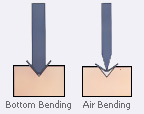
In air bending the dies are made at more of an acute angle (85 degrees or less) than angle to be formed. The only contact between the dies and the material occurs at the tip of male punch and the edges of the female die. The material is "air" bent rather than "coined" or "bottom" bent.
The advisable "Vee" die openings for air bending are:
V= 6 to 8 x material thickness(t), when t< 4 V = 6 to 12 x material thickness(t), when t < 4
In bottom bending the upper and lower dies are usually made with an included angle of 90 degrees to ensure sharp corners on the formed part. In the forming process, the dies strike solidly and squeeze the metal at stroke bottom.
This process requires 3 to 5 times the tonnage needed in air bending. Since more tonnage is required bottoming is seldom performed on steel greater than 12 gauge.
The advisable "Vee" die openings for Bottoming are V = 5 to 6 x material thickness
Bottoming dies are made in matched pairs, according to the thickness and tensile strength of the stock to be formed and the radius needed. The upper and lower dies may require an included 88 or 89 degrees to overcome the spring back of materials with high tensile strength.
| Parameters | Unit |
|---|---|
| Plate Thickness (t) Ultimate Tensile Strength | mm |
| of Plate (S) | Kg / mm2 |
| Bending Length (L) | mm |
| "Vee" Die Opening (V) | mm |
| Minimum internal Radius (R) | mm |
| Minimum Flange (H) | mm |
| Bending Correction Factor (K) | 1.3 |
| Required Tonnage (P) | M.Tonnes |
The basis factors to be considered while selecting a press brake, or calculating the correct setting for operation are The force required for air bending can be calculated from the following formula -. Load, P = K.L.S.t2 / 1000 V Metric Tonnes.
The bending chart given on the next page covers all major bending for plates of 45 Kg/mm2 ultimate tensile strength. The figures given by the chart refer to 1 metre length so they must be multiplied by total plate length to obtain the final required force in Metric Tonnes.
Other Products
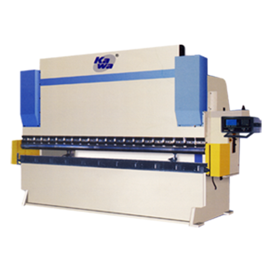
Front Cylinder Press Brake
NC CNC Series
Believing in the Motto of Quality over Quantity
Shailesh Group has firmly believed in delivering quality power press products
all over the world in order to become a pioneer in the field of power press manufacturing.